SKE 80GHz Radar Level Meter: Diagnostics and Condition Monitoring
To ensure the long-term stable, accurate, and reliable operation of SKE's 80GHz radar level meter and to make the most of its high-frequency radar ranging and high-precision measurement capabilities, regular condition monitoring and fault diagnosis are essential. This article systematically covers the key monitoring parameters, built-in diagnostic functions, echo curve analysis methods, and fault code handling procedures for the 80GHz radar level meter, providing a standardized technical reference for routine maintenance, condition assessment, and troubleshooting.
I. Core Continuous Monitoring Parameters
The core diagnostic parameters of SKE's 80GHz radar level meter can be read via the local display or the communication interface. Because the device relies on an 80GHz high-frequency radar signal for measurement, it is highly sensitive to signal conditions and operating environment. Continuously monitoring these parameter values and their trends allows potential issues to be identified early, avoiding measurement inaccuracies and signal anomalies. The normal ranges and monitoring significance of each key parameter are as follows:
Echo strength: the amplitude of the echo signal corresponding to the true level. Given the characteristics of SKE's 80GHz high-frequency measurement, under high-dielectric-constant media conditions the normal value should be greater than 20 dB. The higher the echo strength, the better the signal quality and the more assured the high-frequency measurement accuracy; a low value can easily cause measurement fluctuation or signal loss, undermining the precision advantage of high-frequency measurement.
Echo threshold: the minimum signal level at which the device recognizes a valid echo, with a default value of 12 dB; it can be manually adjusted to suit various measurement scenarios. If the threshold is set too high, weak but genuine level echoes may be filtered out, resulting in missing measurement data; if set too low, ambient noise can be introduced, causing measurement interference and data distortion, preventing the 80GHz radar's core advantages of interference resistance and high precision from being realized.
Gain: the amplification factor applied to the received signal, which can be set automatically or manually to suit SKE's 80GHz radar signal reception mechanism. The gain value directly reflects on-site signal conditions; if the gain remains elevated over a long period, it usually indicates abnormal signal reception caused by antenna fouling, installation deviation, or similar issues, and should be promptly investigated during maintenance.
Internal temperature: the operating temperature of the electronic components inside SKE's 80GHz radar level meter, with a standard operating range of -40°C to +80°C. When the temperature approaches or exceeds this range, the device triggers a Bit7 alarm, the RF module shuts down, and the instrument stops normal measurement — preventing equipment damage and measurement error under high- or low-temperature conditions.
Signal quality (SNR): the core indicator for comprehensively evaluating the quality of the 80GHz radar signal, with no fixed standard value. The higher the SNR and the smaller its fluctuation, the more stable the high-frequency signal and the more accurate the measurement data; large fluctuations indicate unfavorable site conditions such as electromagnetic interference or equipment vibration, which can affect high-frequency measurement performance.
II. How to Use the Device's Diagnostic Functions
SKE's 80GHz radar level meter features built-in professional diagnostic tools, optimized for the characteristics of high-frequency radar measurement. These tools allow the device's operating status to be checked at a glance and the integrity of the high-frequency signal chain to be verified, helping maintenance staff quickly locate problems and keep the device running stably. The main functions are operated as follows:
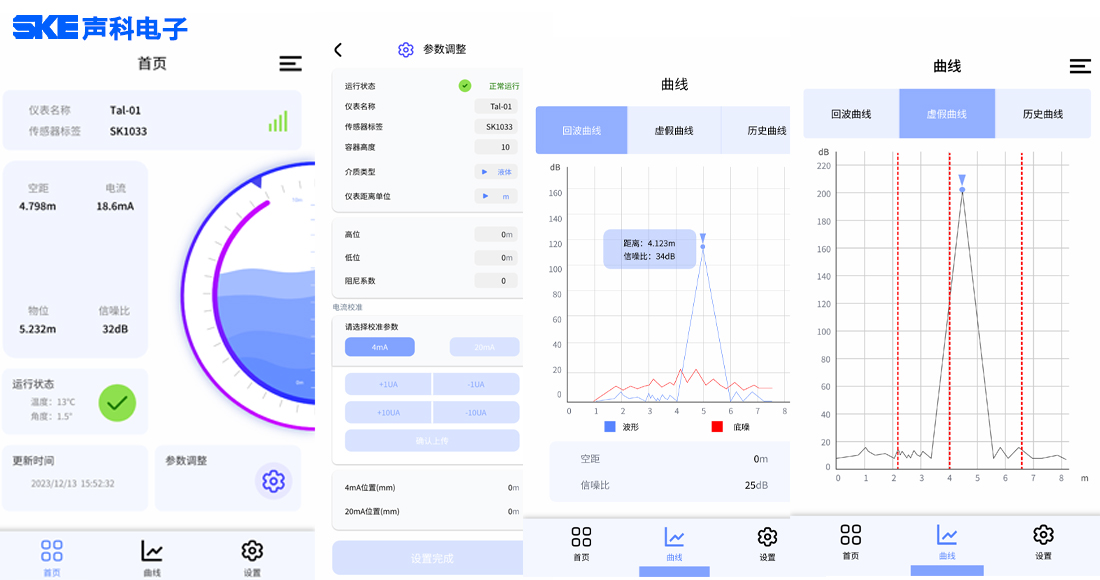
Waveform view function: go to [Diagnostics Settings] → [View Waveform] on the instrument to switch between the real-time echo curve, the learned false-echo curve, and the historical level trend curve, giving a precise view of the 80GHz radar signal reflection status and level measurement conditions, and enabling quick identification of high-frequency signal anomalies.
Simulation verification function: enable the current simulation function under [Diagnostics Settings] → [Simulation] to independently verify the transmission accuracy and operating validity of the entire high-frequency signal chain of SKE's 80GHz radar level meter, without relying on actual level conditions — quickly pinpointing chain faults and ensuring the device's measurement accuracy meets requirements.
III. Key Points for Echo Curve Analysis
The echo curve is the core basis for analyzing the signal status and identifying anomalies in SKE's 80GHz radar level meter. It directly reflects the on-site signal reflection characteristics of the 80GHz high-frequency radar and is precisely suited to the device's high-precision measurement requirements. The parameters and signal characteristics of each dimension are explained below:
The horizontal axis of the curve represents measurement distance, in meters or feet, with the installation position of SKE's 80GHz radar level meter as the starting point; the vertical axis represents signal strength, in decibels (dB), indicating the strength of the high-frequency signal.
True level echo: a prominent peak shown in the curve, whose horizontal-axis position corresponds to the actual level height — this is the valid core signal used by the 80GHz radar for precise level calculation.
False echoes: abnormal peaks other than the true level echo, mainly caused by reflections from the tank wall or internal tank structures. These are invalid interference signals that can disrupt recognition of the 80GHz high-frequency signal and affect measurement accuracy.
Noise signal: small, irregular fluctuations in the curve caused by factors such as on-site electromagnetic interference and vibration of the equipment or tank, which reduce the stability of the 80GHz radar signal and slightly affect measurement accuracy.
Signal threshold: the criterion used to distinguish valid echoes from noise signals. Only signals above the threshold are recognized, processed, and output as measurement data by the device — a key condition for ensuring the high-precision, stable measurement of SKE's 80GHz radar level meter.
IV. Fault Diagnosis Code Handling Procedure
When SKE's 80GHz radar level meter triggers a fault alarm and displays a fault code, a standardized step-by-step procedure should be followed to efficiently troubleshoot and resolve the abnormality and quickly restore the device's high-frequency, high-precision measurement performance. The procedure is as follows:
First, fully record the device's fault code (e.g., E40) to ensure the fault information is accurate; second, consult SKE's 80GHz radar level meter fault code manual to make a preliminary determination of the fault type and cause; third, refer to Section 9.7 of the manual for initial response measures and carry out basic checks and corrective actions; fourth, if the fault cannot be resolved through preliminary troubleshooting, compile complete information including the instrument model, serial number, fault symptoms, and echo curve chart, and contact the manufacturer's technical support for professional servicing.
Related News
SKE 80GHz Radar Level Meter: Diagnostics and Condition Monitoring
A guide to condition monitoring and fault diagnosis for SKE's 80GHz radar level meter, covering key parameters, built-in diagnostic tools, echo curve analysis a...
SKE 80GHz Radar Level Meter and Clamp-On Level Switch Pass German TÜV SIL2/SIL3 Functional Safety Ce
SKE Electronics has officially received SIL2/SIL3 Functional Safety certificates from TÜV Nord Germany, marking a major breakthrough in functional safety for it...